Boost Gauge Vacuum Line Diagram . the following instructions are for the installation of your boost / vacuum gauge. Do not over tighten the sealing nut or you will damage the. electronic boost/vac gauges are equipped with an auto zero function used to compensate for operation at varying. a vacuum gauge measures the vacuum created as the engine draws air into its cylinders. A boost gauge measures the. for pressure gauges, use a 1/8” adapter, a ferrule and a sealing nut. electric boost/vac gauges are equipped with an auto zero function used to compensate for operation at varying altitudes. Before you begin, lay out all items and. on centrifugal supercharged, turbo, and “blow through” applications, you may reference vacuum from a vacuum line from the base. these types of gauges measure the vacuum and/or pressure existing within the intake manifold of the vehicle.
from www.evolutionm.net
the following instructions are for the installation of your boost / vacuum gauge. A boost gauge measures the. on centrifugal supercharged, turbo, and “blow through” applications, you may reference vacuum from a vacuum line from the base. electric boost/vac gauges are equipped with an auto zero function used to compensate for operation at varying altitudes. Do not over tighten the sealing nut or you will damage the. these types of gauges measure the vacuum and/or pressure existing within the intake manifold of the vehicle. electronic boost/vac gauges are equipped with an auto zero function used to compensate for operation at varying. a vacuum gauge measures the vacuum created as the engine draws air into its cylinders. for pressure gauges, use a 1/8” adapter, a ferrule and a sealing nut. Before you begin, lay out all items and.
Vacuum/Boost Line Question EvolutionM Mitsubishi Lancer and Lancer
Boost Gauge Vacuum Line Diagram a vacuum gauge measures the vacuum created as the engine draws air into its cylinders. a vacuum gauge measures the vacuum created as the engine draws air into its cylinders. electric boost/vac gauges are equipped with an auto zero function used to compensate for operation at varying altitudes. the following instructions are for the installation of your boost / vacuum gauge. on centrifugal supercharged, turbo, and “blow through” applications, you may reference vacuum from a vacuum line from the base. these types of gauges measure the vacuum and/or pressure existing within the intake manifold of the vehicle. electronic boost/vac gauges are equipped with an auto zero function used to compensate for operation at varying. A boost gauge measures the. Do not over tighten the sealing nut or you will damage the. Before you begin, lay out all items and. for pressure gauges, use a 1/8” adapter, a ferrule and a sealing nut.
From ilexsayaka.blogspot.com
boost gauge vacuum line diagram IlexSayaka Boost Gauge Vacuum Line Diagram electronic boost/vac gauges are equipped with an auto zero function used to compensate for operation at varying. Before you begin, lay out all items and. the following instructions are for the installation of your boost / vacuum gauge. a vacuum gauge measures the vacuum created as the engine draws air into its cylinders. Do not over tighten. Boost Gauge Vacuum Line Diagram.
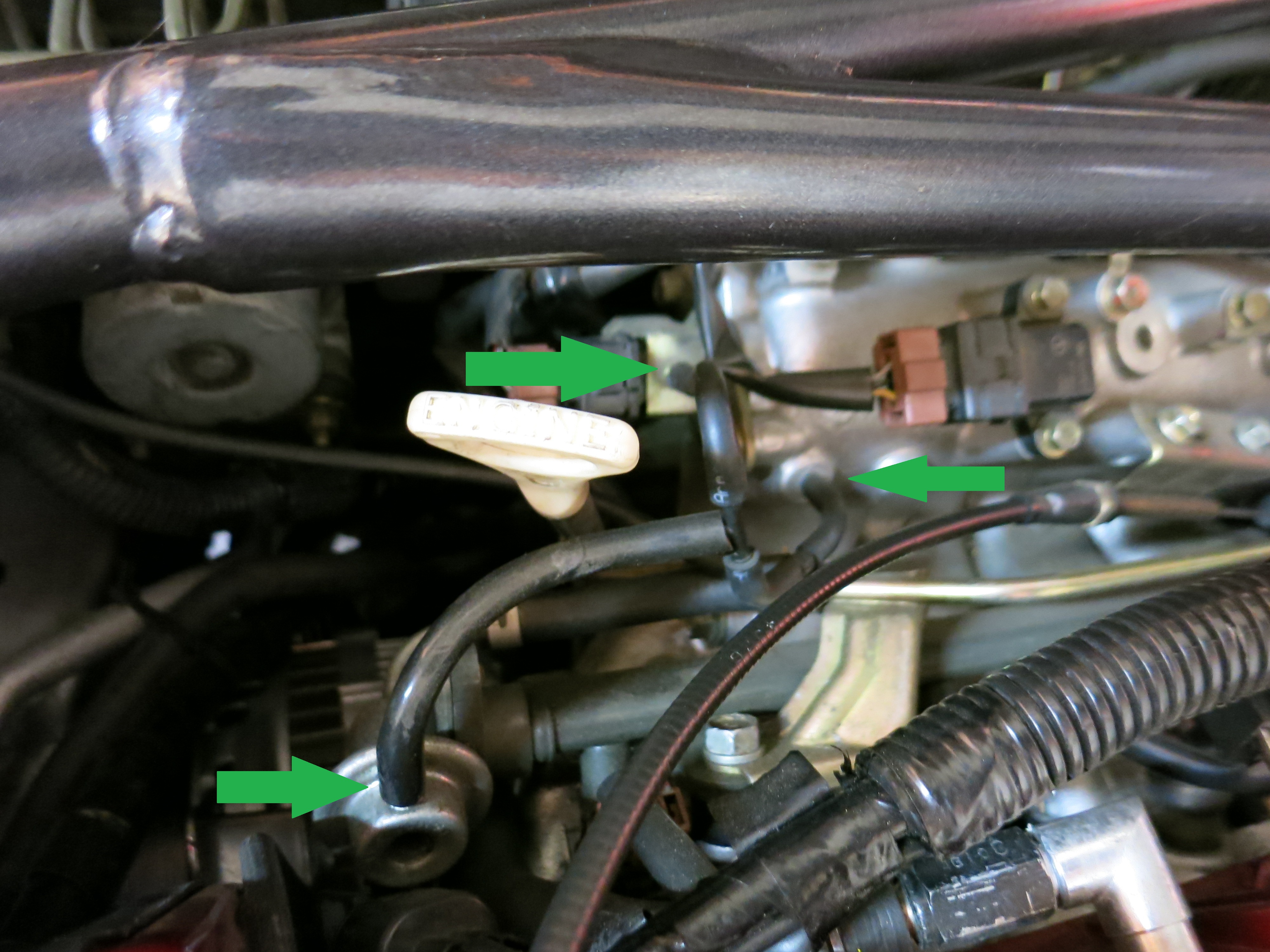
From www.dsmtuners.com
Vacuum line routing ?? DSMtuners Boost Gauge Vacuum Line Diagram these types of gauges measure the vacuum and/or pressure existing within the intake manifold of the vehicle. a vacuum gauge measures the vacuum created as the engine draws air into its cylinders. A boost gauge measures the. for pressure gauges, use a 1/8” adapter, a ferrule and a sealing nut. on centrifugal supercharged, turbo, and “blow. Boost Gauge Vacuum Line Diagram.
From circuitmanualkohler.z19.web.core.windows.net
Turbo Car Vacuum Line Diagram Boost Gauge Vacuum Line Diagram on centrifugal supercharged, turbo, and “blow through” applications, you may reference vacuum from a vacuum line from the base. the following instructions are for the installation of your boost / vacuum gauge. Do not over tighten the sealing nut or you will damage the. electric boost/vac gauges are equipped with an auto zero function used to compensate. Boost Gauge Vacuum Line Diagram.
From www.americanmuscle.com
How to Install Auto Meter Hoonigan Boost/Vacuum Gauge 30 psi Boost Gauge Vacuum Line Diagram A boost gauge measures the. on centrifugal supercharged, turbo, and “blow through” applications, you may reference vacuum from a vacuum line from the base. the following instructions are for the installation of your boost / vacuum gauge. Do not over tighten the sealing nut or you will damage the. electric boost/vac gauges are equipped with an auto. Boost Gauge Vacuum Line Diagram.
From diagramwiringschema.blogspot.com
Boost Gauge Vacuum Line Diagram diagramwirings Boost Gauge Vacuum Line Diagram A boost gauge measures the. Do not over tighten the sealing nut or you will damage the. electronic boost/vac gauges are equipped with an auto zero function used to compensate for operation at varying. electric boost/vac gauges are equipped with an auto zero function used to compensate for operation at varying altitudes. Before you begin, lay out all. Boost Gauge Vacuum Line Diagram.
From www.svtperformance.com
Whipple Install Boost Vacuum Diagrams Boost Gauge Vacuum Line Diagram the following instructions are for the installation of your boost / vacuum gauge. Before you begin, lay out all items and. electronic boost/vac gauges are equipped with an auto zero function used to compensate for operation at varying. a vacuum gauge measures the vacuum created as the engine draws air into its cylinders. on centrifugal supercharged,. Boost Gauge Vacuum Line Diagram.
From www.nissanpatrol.com.au
Boost gauge install Boost Gauge Vacuum Line Diagram Do not over tighten the sealing nut or you will damage the. these types of gauges measure the vacuum and/or pressure existing within the intake manifold of the vehicle. electric boost/vac gauges are equipped with an auto zero function used to compensate for operation at varying altitudes. the following instructions are for the installation of your boost. Boost Gauge Vacuum Line Diagram.
From www.f150ecoboost.net
tubing placement for boost gauge F150 Ecoboost Forum Boost Gauge Vacuum Line Diagram the following instructions are for the installation of your boost / vacuum gauge. Before you begin, lay out all items and. electronic boost/vac gauges are equipped with an auto zero function used to compensate for operation at varying. A boost gauge measures the. electric boost/vac gauges are equipped with an auto zero function used to compensate for. Boost Gauge Vacuum Line Diagram.
From resolutionsforyou.com
A Comprehensive Guide to the Ej205 Vacuum Line Diagram Boost Gauge Vacuum Line Diagram the following instructions are for the installation of your boost / vacuum gauge. on centrifugal supercharged, turbo, and “blow through” applications, you may reference vacuum from a vacuum line from the base. Before you begin, lay out all items and. Do not over tighten the sealing nut or you will damage the. electronic boost/vac gauges are equipped. Boost Gauge Vacuum Line Diagram.
From www.evolutionm.net
Boost Gauge and MBC install Page 4 Boost Gauge Vacuum Line Diagram a vacuum gauge measures the vacuum created as the engine draws air into its cylinders. the following instructions are for the installation of your boost / vacuum gauge. on centrifugal supercharged, turbo, and “blow through” applications, you may reference vacuum from a vacuum line from the base. A boost gauge measures the. electric boost/vac gauges are. Boost Gauge Vacuum Line Diagram.
From www.youtube.com
How to install a boost gauge into your vehicle YouTube Boost Gauge Vacuum Line Diagram electronic boost/vac gauges are equipped with an auto zero function used to compensate for operation at varying. a vacuum gauge measures the vacuum created as the engine draws air into its cylinders. on centrifugal supercharged, turbo, and “blow through” applications, you may reference vacuum from a vacuum line from the base. for pressure gauges, use a. Boost Gauge Vacuum Line Diagram.
From mectips.com
BRAKE VACUUM BOOSTER Mechanical Engineering Boost Gauge Vacuum Line Diagram electronic boost/vac gauges are equipped with an auto zero function used to compensate for operation at varying. the following instructions are for the installation of your boost / vacuum gauge. A boost gauge measures the. Before you begin, lay out all items and. Do not over tighten the sealing nut or you will damage the. these types. Boost Gauge Vacuum Line Diagram.
From kaylsheemi.blogspot.com
8+ boost gauge vacuum line diagram KaylSheemi Boost Gauge Vacuum Line Diagram a vacuum gauge measures the vacuum created as the engine draws air into its cylinders. electronic boost/vac gauges are equipped with an auto zero function used to compensate for operation at varying. electric boost/vac gauges are equipped with an auto zero function used to compensate for operation at varying altitudes. Before you begin, lay out all items. Boost Gauge Vacuum Line Diagram.
From www.2carpros.com
Vacuum Lines Diagram How Do I Get a Vacuum Line Diagram for My Boost Gauge Vacuum Line Diagram Do not over tighten the sealing nut or you will damage the. Before you begin, lay out all items and. on centrifugal supercharged, turbo, and “blow through” applications, you may reference vacuum from a vacuum line from the base. for pressure gauges, use a 1/8” adapter, a ferrule and a sealing nut. electronic boost/vac gauges are equipped. Boost Gauge Vacuum Line Diagram.
From www.cobaltss.net
Factory Vacuum and Boost Lines Diagram Cobalt SS Network Boost Gauge Vacuum Line Diagram on centrifugal supercharged, turbo, and “blow through” applications, you may reference vacuum from a vacuum line from the base. A boost gauge measures the. these types of gauges measure the vacuum and/or pressure existing within the intake manifold of the vehicle. electronic boost/vac gauges are equipped with an auto zero function used to compensate for operation at. Boost Gauge Vacuum Line Diagram.
From www.agcoauto.com
AGCO Automotive Repair Service Baton Rouge, LA Detailed Auto Topics Boost Gauge Vacuum Line Diagram these types of gauges measure the vacuum and/or pressure existing within the intake manifold of the vehicle. the following instructions are for the installation of your boost / vacuum gauge. A boost gauge measures the. for pressure gauges, use a 1/8” adapter, a ferrule and a sealing nut. a vacuum gauge measures the vacuum created as. Boost Gauge Vacuum Line Diagram.
From wirelistclericals.z21.web.core.windows.net
Boost Gauge Vacuum Line Diagram Boost Gauge Vacuum Line Diagram electric boost/vac gauges are equipped with an auto zero function used to compensate for operation at varying altitudes. on centrifugal supercharged, turbo, and “blow through” applications, you may reference vacuum from a vacuum line from the base. the following instructions are for the installation of your boost / vacuum gauge. Do not over tighten the sealing nut. Boost Gauge Vacuum Line Diagram.
From enginelistchester.z5.web.core.windows.net
Boost Gauge Vacuum Line Diagram Boost Gauge Vacuum Line Diagram these types of gauges measure the vacuum and/or pressure existing within the intake manifold of the vehicle. Before you begin, lay out all items and. on centrifugal supercharged, turbo, and “blow through” applications, you may reference vacuum from a vacuum line from the base. Do not over tighten the sealing nut or you will damage the. electronic. Boost Gauge Vacuum Line Diagram.